Autonomous Platform for Kiwifruit Orchards
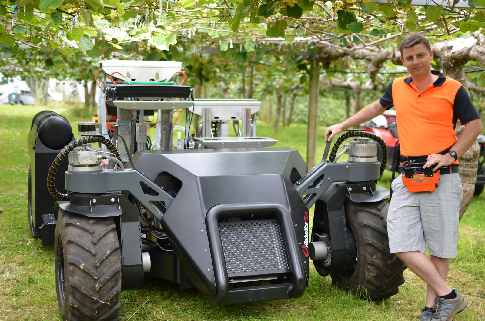
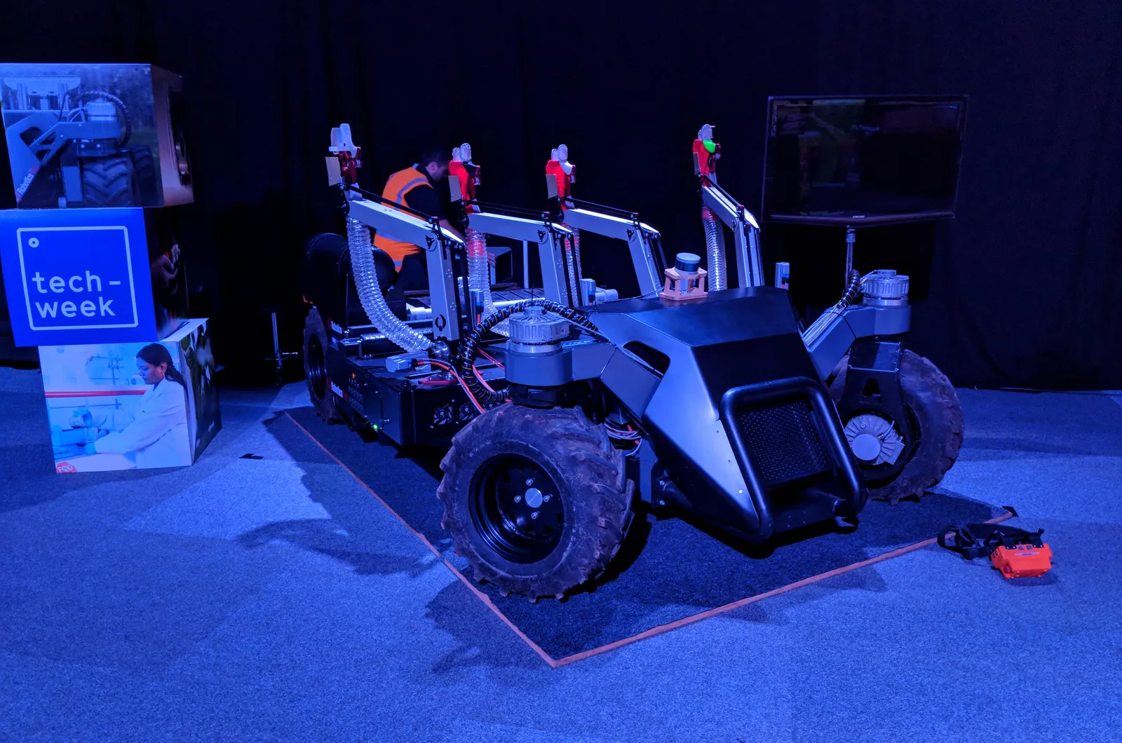
Between 2015 and 2018, a $10M government-funded project set out to build autonomous robots for kiwifruit orchards in New Zealand. Four institutions were involved: the University of Waikato, the University of Auckland, Plant and Food Research, and Robotics Plus (commercial partner). The goal was to automate the most labour-intensive parts of kiwifruit production: harvesting and pollination. My role was developing the AMMP (Autonomous Multi-purpose Mobile Platform), a vehicle that would carry harvesting and pollination modules autonomously through kiwifruit orchards. This post is about the construction of that vehicle.
Pergola canopies and GPS denial
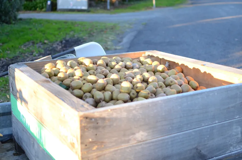
Kiwifruit is New Zealand’s largest horticultural export. What makes kiwifruit orchards unique from a robotics perspective is their structure. Kiwifruit vines grow over a pergola canopy, a flat overhead structure about 1.8 metres off the ground supported by rows of wooden posts. The fruit hangs down from the underside. When the canopy is laden with fruit it sags considerably, bringing the effective clearance down to about 1.4 metres. So the robot needs to drive beneath a low, dense overhead structure. The canopy and surrounding shelter belts also block satellite signals, making satellite navigation infeasible whenever the canopy has foliage.
Designing the platform
The requirements were heavy: 1000 kg payload capacity, fit under that 1.4 m clearance, navigate autonomously without satellite positioning, supply 8 kW of electrical power to onboard modules, and provide a module mounting area low enough for the harvesting arms to reach up into the canopy. It also needed to make headland turns at row ends and lift fruit bins between its rear wheels. Nothing on the market (the ClearPath Warthog being the closest) could meet this combination, so it had to be designed from scratch.

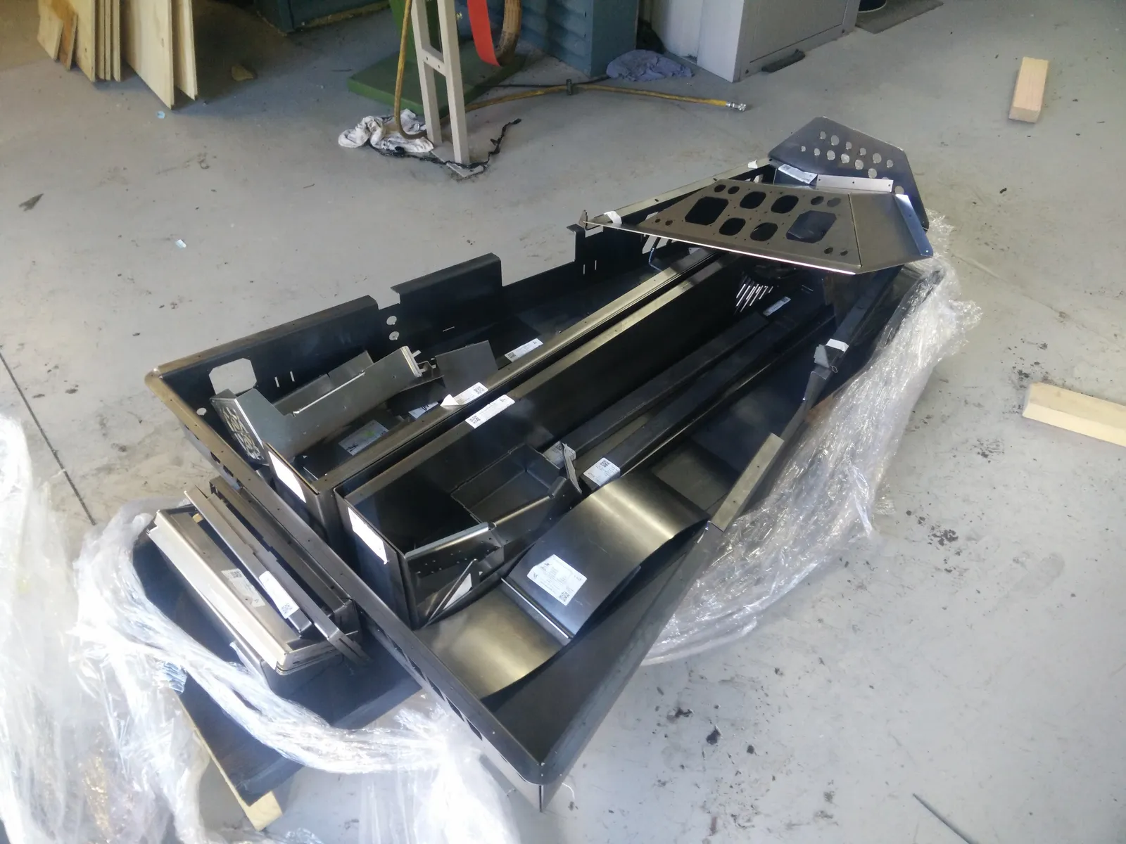
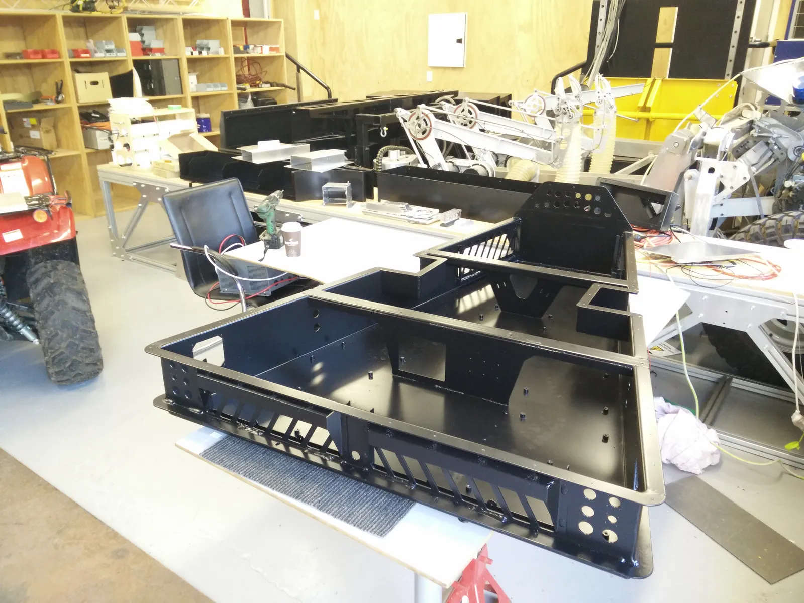
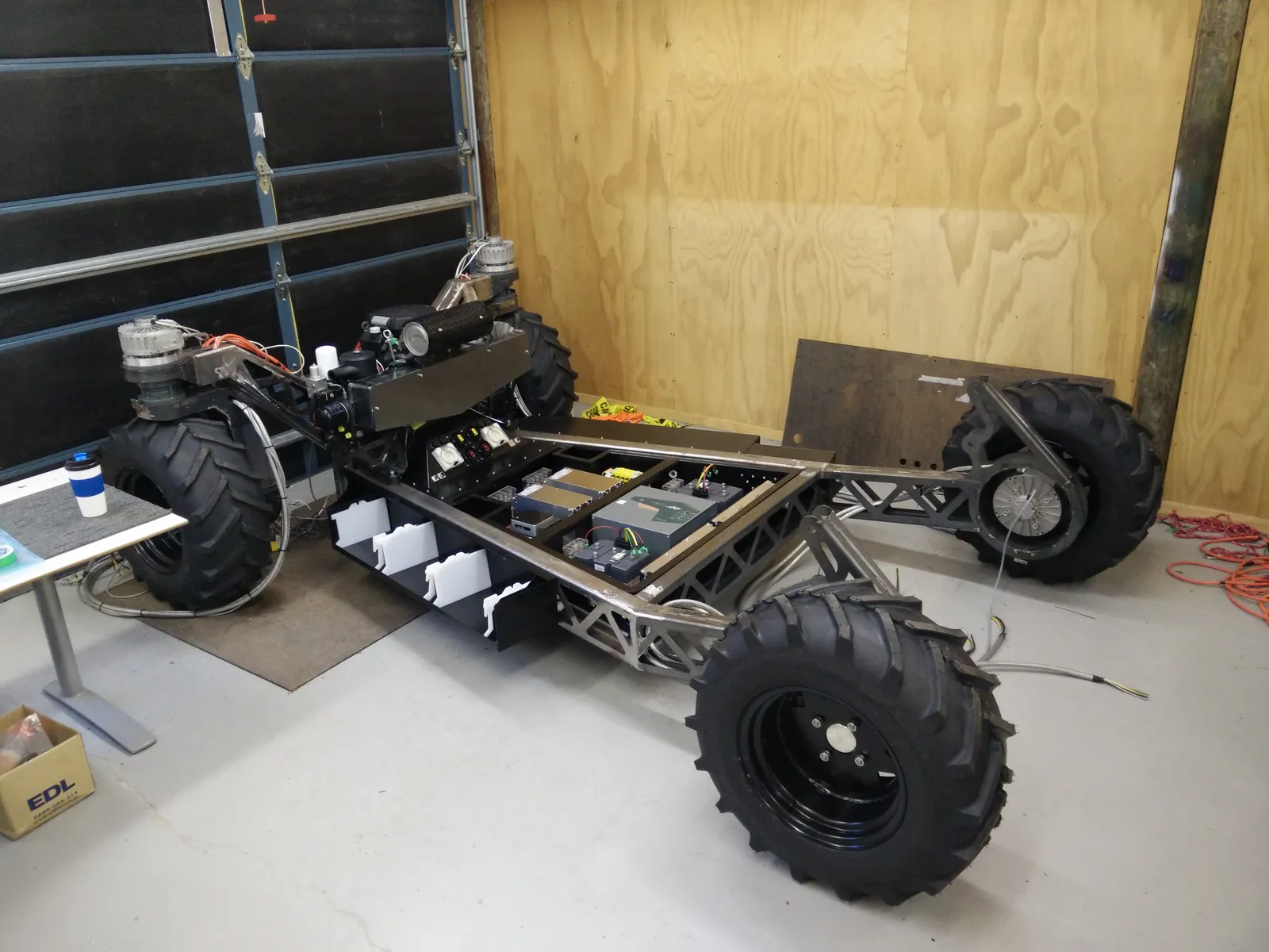
The chassis is assembled from laser-cut and folded 3 mm mild steel sections, welded together on jigs. Much of the folded structure contains triangular cut-outs to reduce mass with minimal impact on rigidity, guided by finite element analysis during design. The bare chassis weighs 190 kg.
At the back, the rear wheels are spaced wide enough to fit a standard kiwifruit bin between them, with a pneumatic bin lifter to pick up and set down full bins. The flat mounting area on top sits just 360 mm off the ground, low enough for harvesting arms to reach up into the canopy overhead.
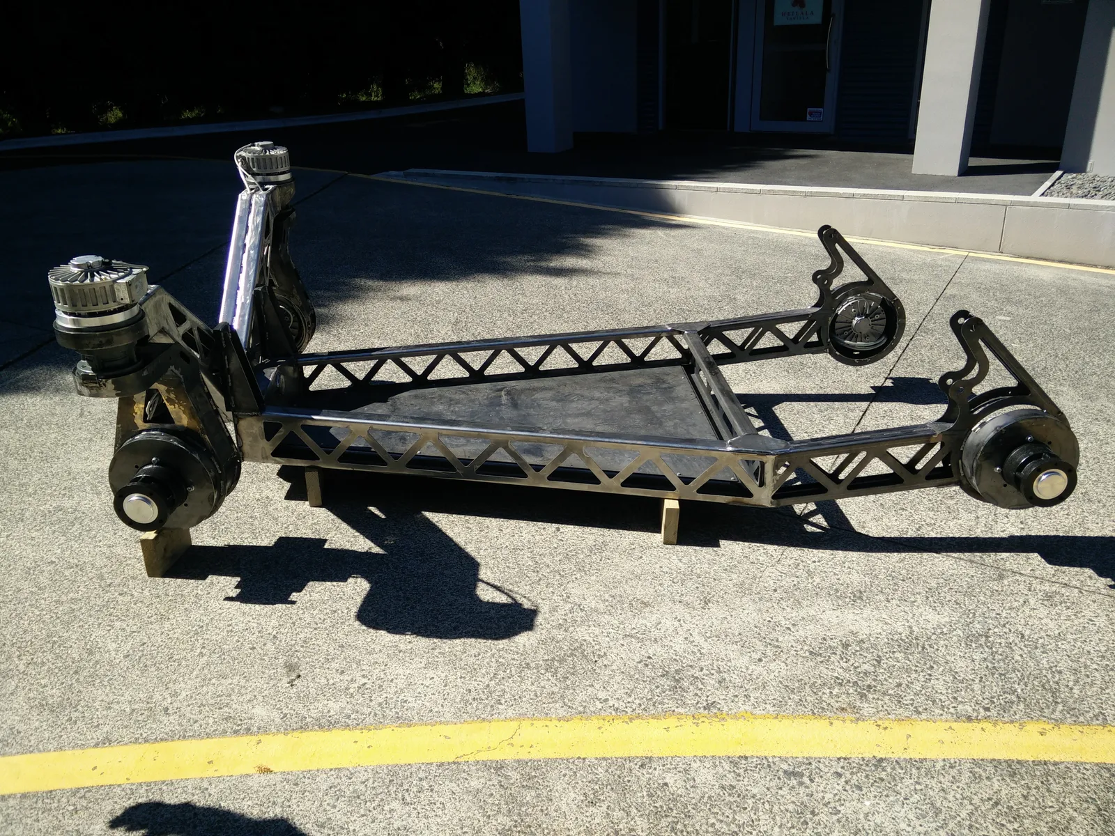
From the bin lifter, the chassis tapers inward toward the front. The triangular space between the rails houses all the electronics: battery packs, motor controllers, contactors, and DC-DC converters, tucked away beneath the module mounting area. The chassis narrows toward the front to give the steered wheels room to turn. Steering uses Ackermann geometry on the front two wheels, each driven by a brushless AC motor through a 64:1 planetary gearbox producing 470 Nm of output torque. The worst-case steering load is overcoming static friction on dry concrete with 500 kg per wheel, which works out to 388 Nm. The 470 Nm available gives a comfortable margin.
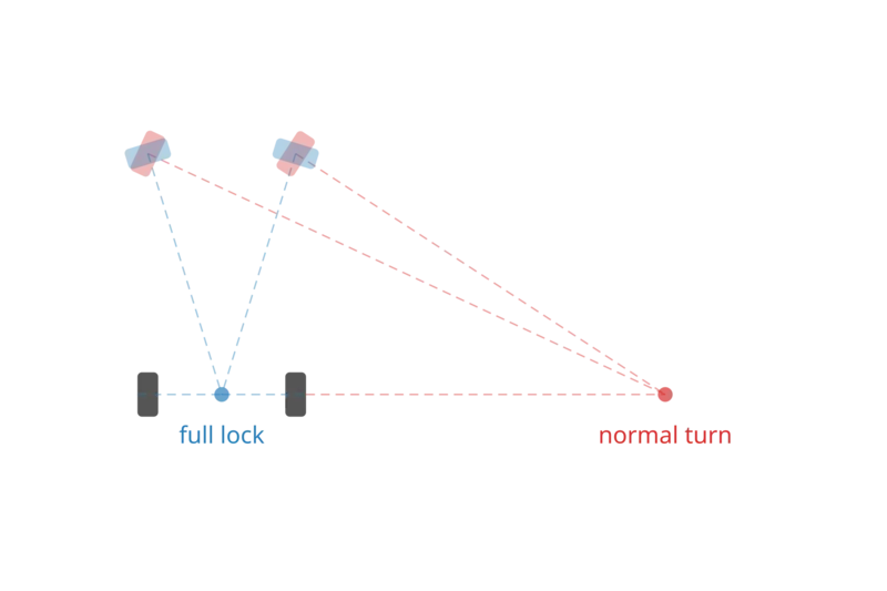
Both steered wheels can rotate 330 degrees before hitting the mechanical stops. At 90 degrees of steering angle the platform turns about the midpoint of the rear axle (the full lock scenario in the image above), giving a calculated turning radius of 3.2 m, confirmed at 3.23 m in testing.
Orchards aren’t flat, and on ground that twists rather than just slopes, a rigid four-wheeled vehicle can end up with a wheel off the ground. A single pivot on the front axle gives the platform a three-point suspension: two fixed rear wheels and a front axle that tilts to follow the terrain, without springs. At 5 km/h operating speed, the soft tyres are sufficient for absorbing shocks and vibrations.
Sizing the drive system
The platform needed to carry up to 1000 kg of module and fruit on top of its own 850 kg kerb weight, plus fuel and fluids. Working backwards from a loaded mass ($m$) of 1900 kg, we calculated the three forces each wheel motor would need to overcome:
- Rolling resistance - how much force it takes just to keep the wheels turning on soft ground. The coefficient of 0.04 is for pneumatic tyres on medium-hard soil (from the Bosch automotive handbook):
- Gradient - the force needed to drive up a slope. Some orchard blocks have serious hills, so we designed for a 20-degree grade:
- Acceleration - the force needed to get up to 10 km/h (2.78 m/s) within 6 seconds:
Adding those up gives 7999 N total. Split across four wheels that’s 2.0 kN per wheel, which translates to 729 Nm of torque at the 0.365 m wheel radius. At 10 km/h the power requirement works out to 5.55 kW per wheel.
We chose Heinzmann hub-mounted permanent-magnet AC motors (PSM-G120) rated at 6.4 kW each. With their integrated 40:1 planetary gearboxes, the output torque was 816 Nm per wheel - comfortably above the 729 Nm requirement. Top speed on paper was 10.3 km/h.
In acceleration testing the platform only reached 9.0 km/h, likely due to a motor controller configuration issue. Using an IMU to measure acceleration, we calculated 930-1046 Nm per wheel on level ground, which is close to the motors’ rated 816 Nm. The motor controllers were configured to allow short bursts of extra torque, which likely accounts for the higher figure.
Building it
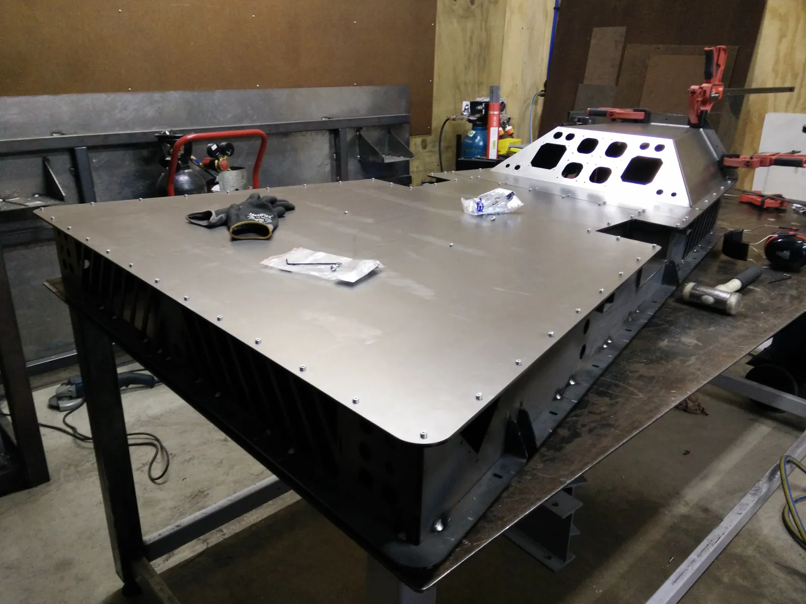
The chassis was designed in SolidWorks and sent to Stainless Design in Hamilton for laser cutting and folding. The parts came back as a flat-pack kit, along with a set of jigs also cut from steel that held everything in alignment during welding. A colleague did most of the MIG welding, with me helping where I could. Finite element analysis (FEA) flagged a stress concentration at the back of the triangle where the rear axle loads converge, so we welded reinforcement plates onto the top and bottom of that area for good measure.
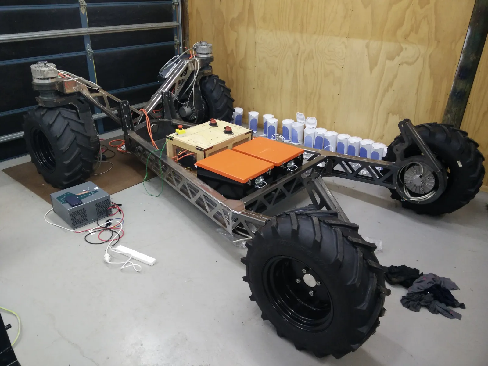
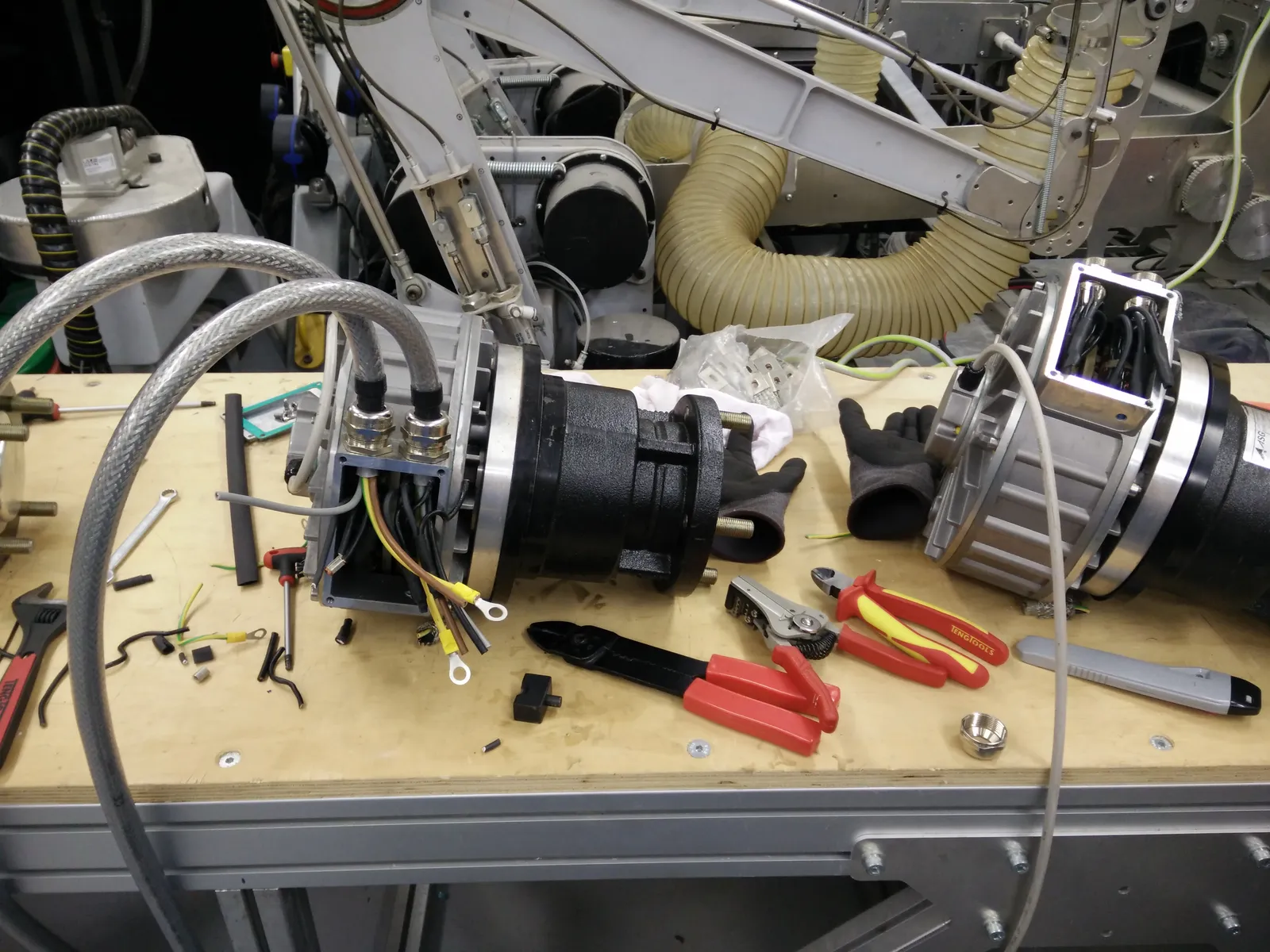
A test fit of the motors before preparing the frame for powder coating. The plate visible in the centre of the triangle was a welding jig, not part of the final platform.
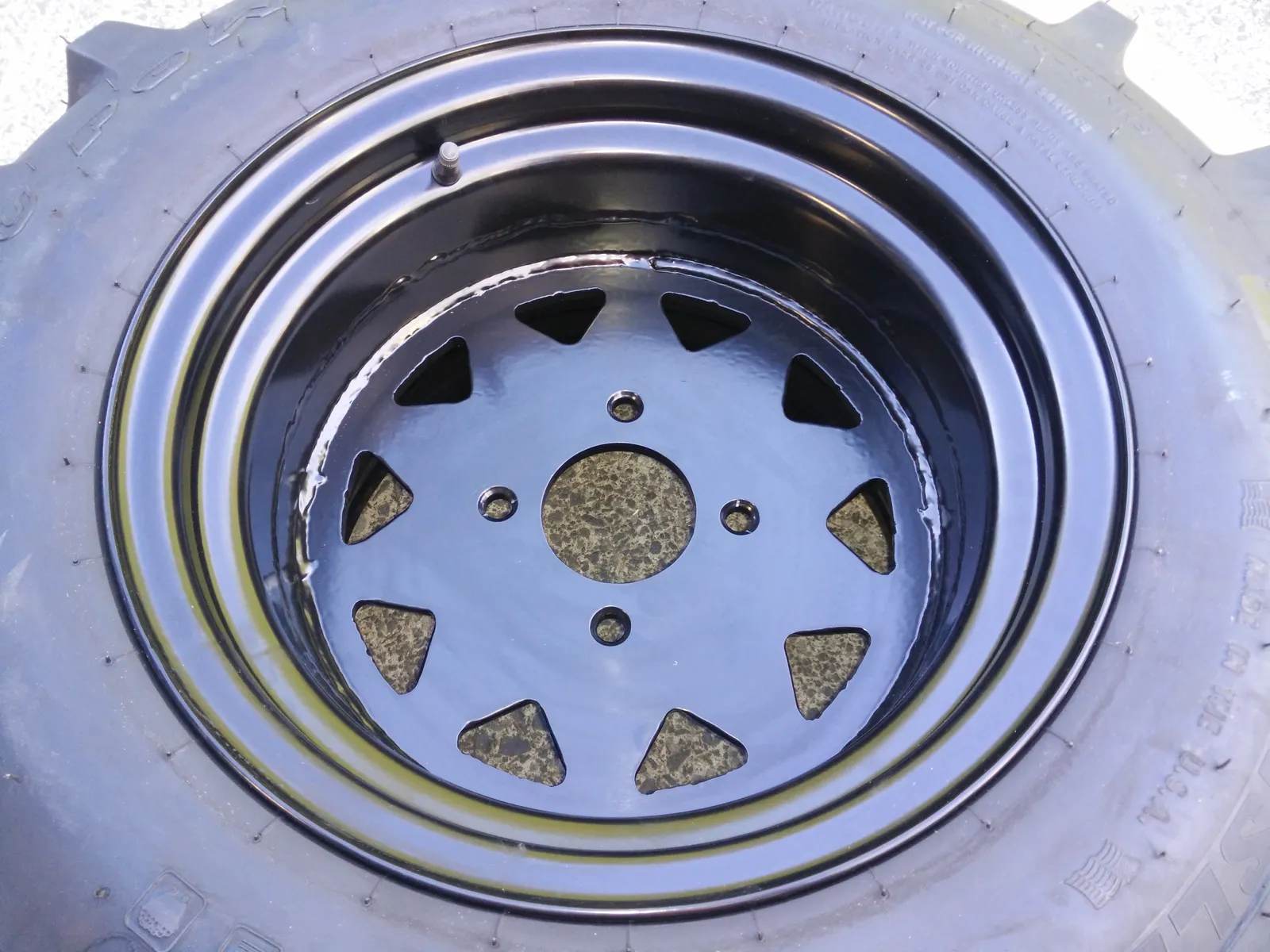
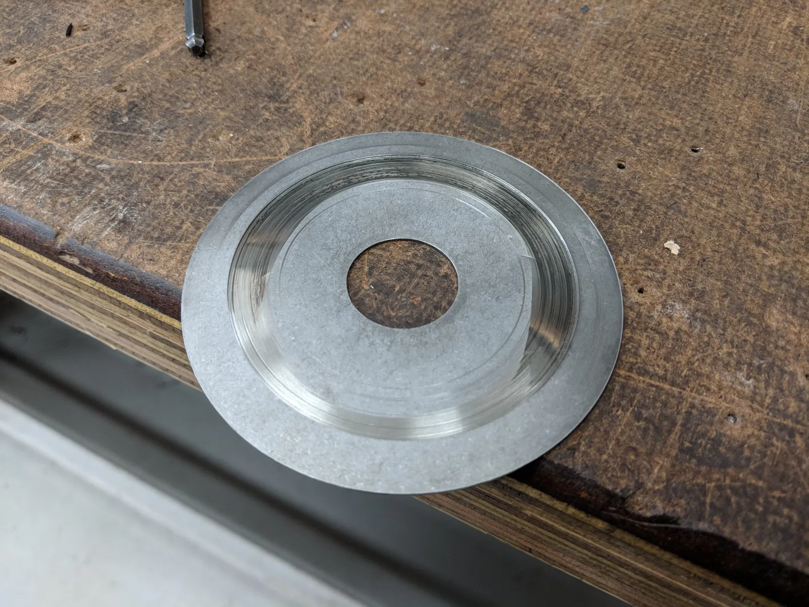
The wheel rims were custom designed so we could control the hub offset precisely, which was important for getting the wheel positions right for the Ackermann steering geometry.
Power system
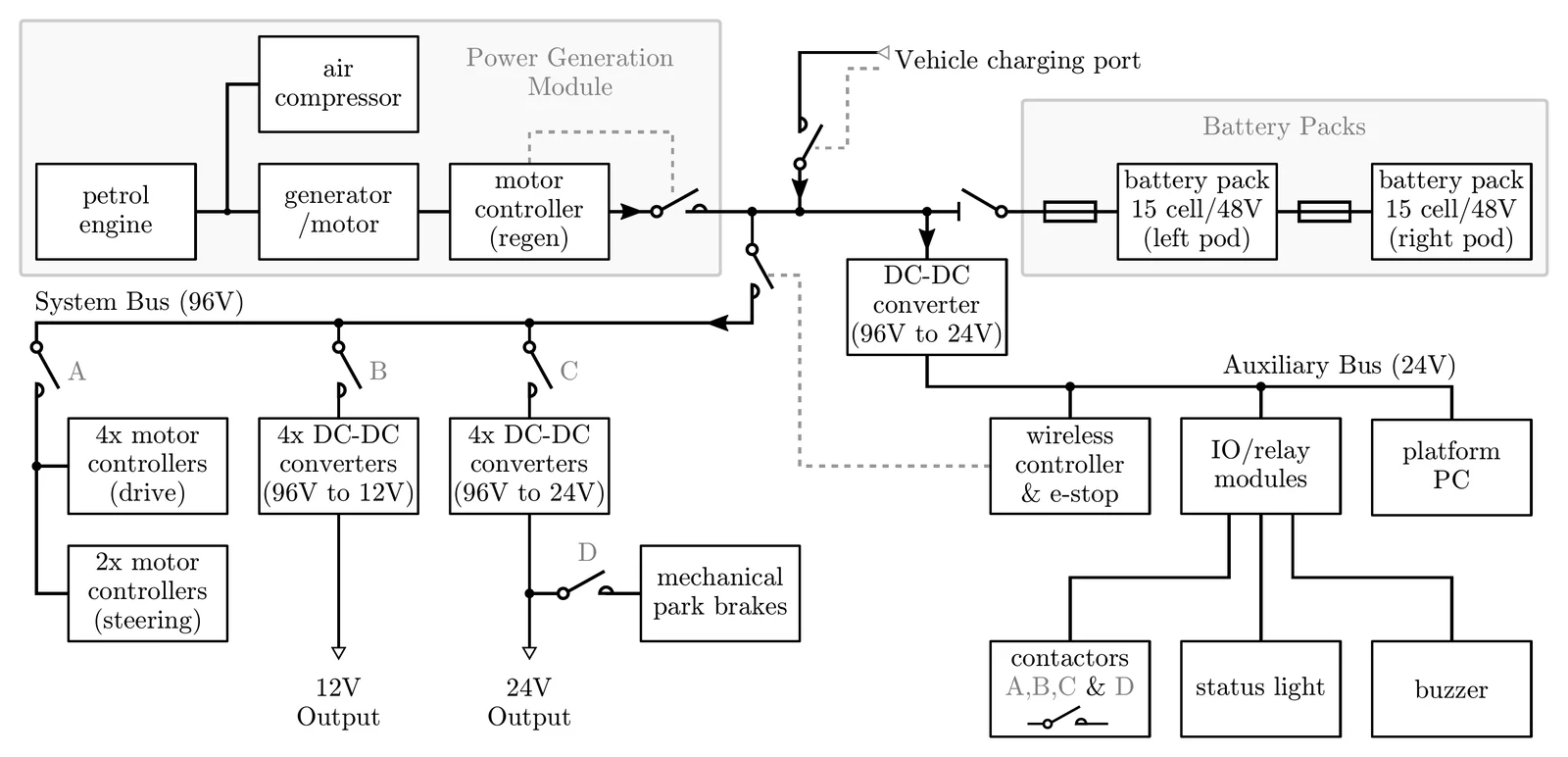
The six traction and steering motors together can consume 30.2 kW. At 48V that would mean 630 A flowing through 24 metres of cabling between the motor controllers and motors. Either the cables would need to be ridiculously thick to handle that current, or we’d waste a lot of power just heating them. Doubling the voltage to 96V halved the current and made the wiring manageable.
For endurance we went with a series-hybrid setup built around a 16 kW Honda petrol engine, bringing the total to seven brushless AC motors on the platform: four drive, two steering, and one generator. A heavy-duty timing belt connected the engine to a brushless AC generator (up to 9.6 kW electrical) and a belt-driven compressor (4.0 kW pneumatic). On-board DC-DC converters stepped the 96V bus down to 12V, 24V, and 230V AC, with a weather-sealed connection panel at the front of the module mounting area providing the interface to whatever module was bolted on top. There was also an external charging port for topping up from mains power without running the engine.
Electrical safety
48V you can touch without too much worry, but 96V can hurt you. Designing the vehicle to be safe while dealing with high-voltage DC power influenced a lot of the decisions that followed.
The chassis was electrically floating, not connected directly to either battery terminal. An isolation monitor watched for any leakage between both the 0V and 96V power buses and the chassis. A single fault, say a positive cable chafing through to the frame, wouldn’t complete a circuit. Both positive and negative would have to contact the chassis simultaneously to create a short, which was far less likely.
The default state of the system was everything disconnected. The contactors that connected the battery packs to the 96V bus required power to stay closed, so if anything went wrong - loss of power, isolation fault, emergency stop - they would open and the batteries would disconnect. If the isolation monitor detected a low-resistance path from either rail to the chassis, it would cut the power holding the contactors closed and the system would shut down.
In order to make the system fail-safe, it needed a way of bootstrapping itself. The 96V bus powered the DC-DC converters, which powered the computers, which controlled the contactors, but the contactors had to be closed before any of that existed. The Honda engine had its own 12V starter battery, so we tapped into that to power the initial contactors that made the 96V bus live. The engine controller handled this bootstrap sequence: close the main contactors from the 12V supply, bring up the 96V bus, start the DC-DC converters, boot the computers, and hand over control.
Because the whole electrical system was isolated from earth ground, there could be a noticeable voltage offset between the platform and anything earthed. You could feel it through a USB cable if you were plugging a laptop in to monitor the CAN bus, for example. To deal with this, whenever the platform was stationary and we needed to connect a computer, we’d plug in the charger. Australian/New Zealand mains plugs have a dedicated earth pin, and that earth was connected to the chassis, which brought everything to the same potential.
Electrical assembly
Orchards are wet and dusty. Pollination involves spraying water into the canopy, driving over gravel stirs up dust, and in the mornings there’s fog and dew on the tall grass. The platform gets left out in the rain and loaded on and off trailers. All the power electronics - motor controllers, contactors, DC-DC converters, and bus bars - needed to survive that, while still getting enough airflow to cool the motor controllers.
The cabinet was assembled from laser-cut and folded mild steel, welded together. Mounting holes, ventilation slots, and cable routing were all cut in at this stage. The lid sealed against a laser-cut rubber gasket, and the cabinet sections were joined with external flanges so that even if water found its way through a bolt hole it was still on the outside. Cables entered through glands, and the connectors on top each had their own weatherproof gaskets.
A cabinet section welded up with its lid and gasket channel visible, and after powder coating. The ventilation slots and external flange bolt holes are visible on both.
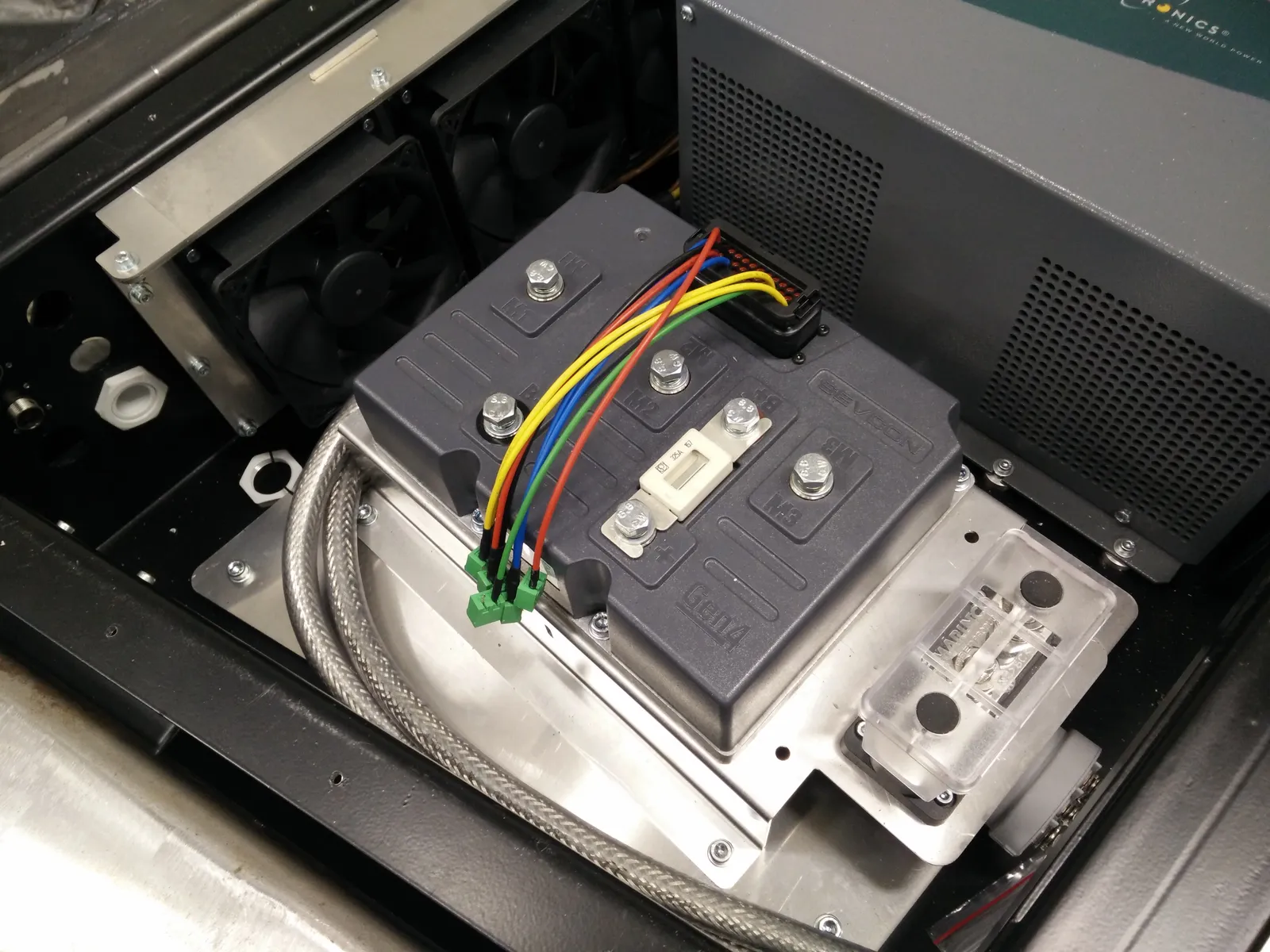
One of six motor controllers (Sevcon Gen4) bolted to its heatsink plate inside the cabinet, with cooling fans behind, drawing air through ventilation slots toward the rear. Next to the controller sits an isolated bus bar and below that a 500 A DC contactor. The mounting plate was designed with provisions for additional heatsinking material underneath the controller, but in practice the thermal conduction into the plate alone was enough to keep them cool, so we never needed it.
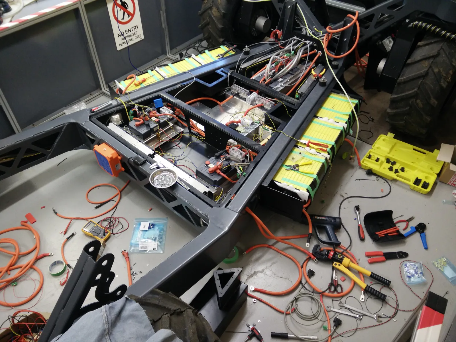
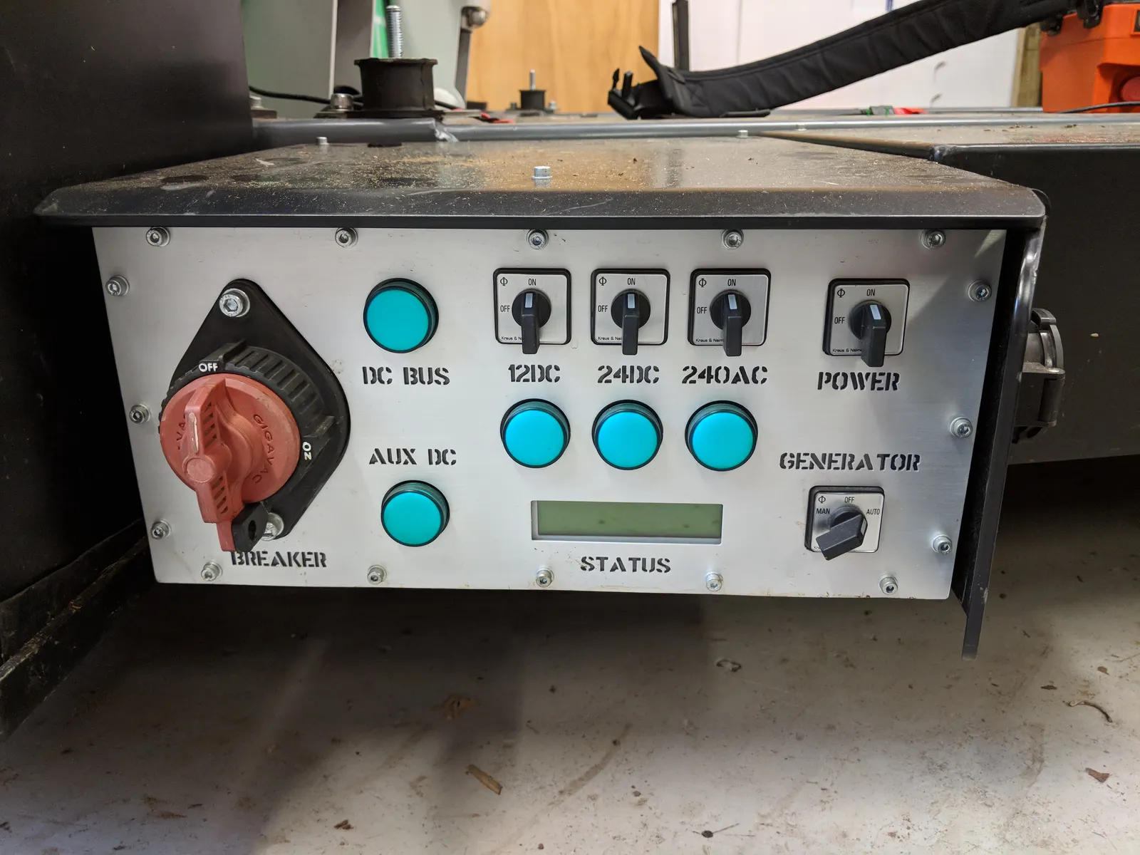
For batteries we used two packs of LiFePO4 cells, fifteen per pack, thirty in series, giving 96V nominal and about 8.6 kWh total. Laser-cut nylon plates slid in between the cells to hold them tight during movement, and could be removed to access individual cells for maintenance. The packs were bottom-balanced with no battery management system. I occasionally checked cell voltages manually, which worked, but in hindsight a proper BMS would have been the smarter choice. A disconnect switch isolated the batteries from the rest of the system - the big red breaker on the left of the control panel below.
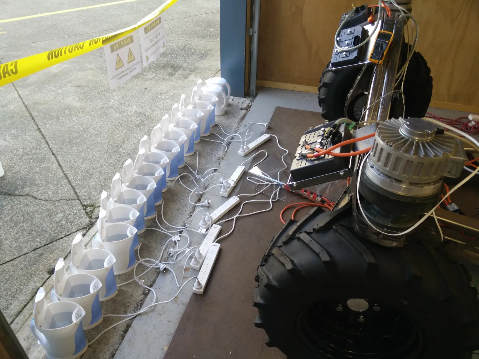
We tested the generator output and peak battery output by wiring fifteen electric jug elements in parallel as an improvised resistive load on the 96V bus.
Onboard computing and control
The platform’s internal computer was an Intel NUC running Ubuntu Server and ROS Kinetic. It communicated directly with the drive and steering motors over CAN bus, ran an Ackermann kinematics node that translated a single steering vector into individual wheel velocity and angle commands for each of the six motors, and controlled the park brakes on the two front steering motors. The brakes used a dog clutch that required power to release, so they would engage automatically if power was lost.
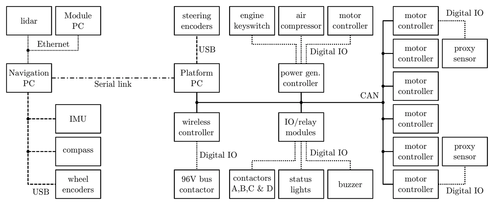
The NUC broadcast a synchronisation message onto the CAN bus every 20 ms. The motor controllers required this message to stay operational - if it stopped, they would lose communication and shut down. The SICK safety controller also monitored these sync messages on the bus, and if the gap exceeded 100 ms it would trigger an emergency stop independently, disconnecting the contactors without any involvement from the NUC.
For manual control we started with a game controller, which was fine for early testing but not something we’d trust with a 1900 kg vehicle in a real orchard. We replaced it with a wireless controller designed for overhead cranes, which had a hardware-level emergency stop and a watchdog that would trigger an emergency stop if the controller went out of range or lost communication: bus contactor open, brakes engaged, all power cut. This was a hard-wired safety circuit, completely independent of the software. The NUC also read the steering encoders over USB and interfaced with a power generation controller over CAN, which managed the engine and compressor.
The platform was designed to be a complete vehicle on its own - you could drive it around with just the crane controller and no other computing attached. For autonomous navigation, a separate PC could connect over a serial link and send steering and drive commands. Serial isn’t an exciting choice, but its main benefit is that it’s a one-to-one channel - whatever process opens the port has exclusive control. With Ethernet, a stale container running in the background or another device on the network could send commands to the platform without anyone realising. On a vehicle this size, that kind of mistake could kill somebody.
Bringing it to life
The motor controllers supported a master-slave mode over CAN bus, but only for simple configurations like one master and one slave. The protocol wasn’t publicly documented, and there was no way to coordinate six motors with custom steering geometry through their standard interface. To figure it out, I configured two controllers into master-slave mode and used a CAN bus analyser to capture every packet the master sent. By working through the captured traffic I reverse-engineered the protocol: the message formats, timing, and handshake sequences the slaves expected. Then I wrote a ROS driver that made the NUC impersonate a Sevcon master. All six motor controllers were flashed as slaves, and each one thought it was talking to a real Sevcon master when it was actually taking commands from a ROS node.
The startup sequence alone was a challenge. The CAN bus had to be powered first, then each controller needed to be initialised in the right order with the right timing. Miss a step or get the timing wrong and the controllers would drop into an error state and refuse to start. Relays controlled the power-on sequence: bring up the bus, establish communication, let each controller enable its own relay, then transition to the running state. In the following video you can see that boot sequence completing for the first time: the NUC initialising communication with all six slaves over CAN, the controllers powering up, and then all four drive wheels and both steering wheels moving together.
Lessons learnt
Throughout the project, the steering motors would randomly drop out mid-operation, and got progressively worse over time. The issue didn’t seem to present itself on the drive motors, just the steering motors. To reduce the impact of these dropouts, which could happen at any moment, the system would auto-recover by coming to a complete stop, re-homing the steering wheels, and continuing. It kept the platform moving but never got me any closer to the cause, and reduced the issue to more of an annoyance than anything - especially when it occurred while crossing public roads.
For a long time I assumed the cause was electrical. There’s a lot of high-power switching going on inside the cabinet, and I thought electromagnetic interference might be corrupting the encoder signals. I tried grounded shielding between compartments, screened signal cables, replacement encoders, and even soldered monitoring wires directly onto encoder pins to watch the signals on an oscilloscope. But the dropouts were so infrequent, and the timing so unpredictable, that I could never catch one in the act.
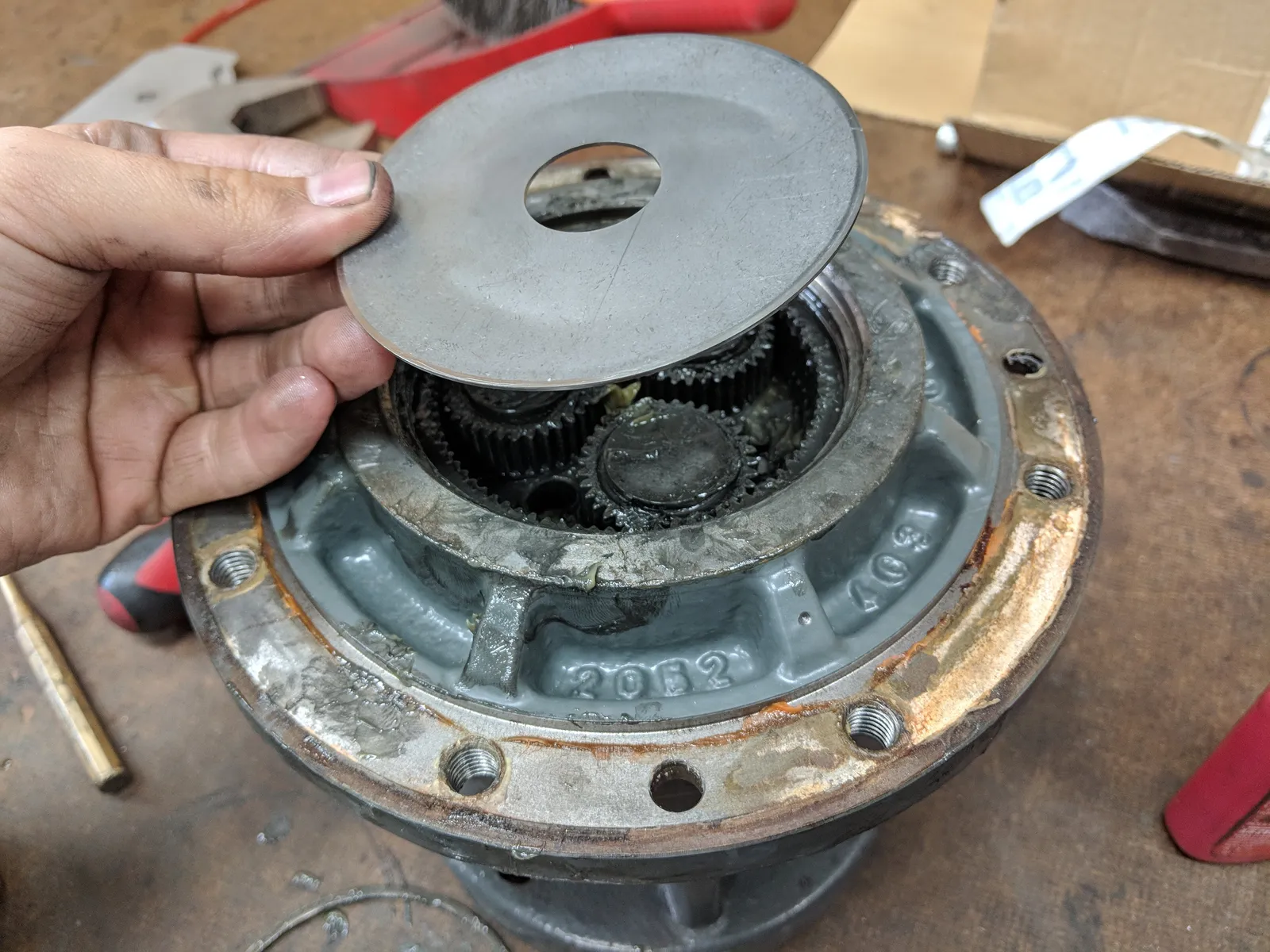
Late in the project, after an incident where the front pivot got bent, we noticed severe play on one of the steering motor gearboxes. Each front steering wheel was actuated by a motor and gearbox mounted vertically above it, with no other bearing, so the full weight of the front of the vehicle passed directly through each gearbox. When we pulled one apart, the planetary gears had worn against the cover plate under a load the gearbox was never rated for. If that wear created enough play to briefly shift the encoder magnet relative to its Hall effect sensor, it would explain the intermittent faults - and why only the steering motors were affected.
In hindsight, fitting the front wheels with their own bearings would have taken the load off the gearboxes entirely. Switching to absolute encoders would have helped too. With the relative encoders, the wheels had to go through a homing routine every time the vehicle started, and if the platform was parked up against something and a wheel couldn’t physically move, the homing would fail and the vehicle would never reach a ready state.
The belt-driven compressor made sense on paper. Driving it mechanically from the engine is more efficient than converting to electricity and back to mechanical movement. But it coupled the air supply to the engine, so any time the tank pressure dropped the engine would start automatically - even when the batteries had plenty of charge and we were running on electric power. The air tank was big enough that this didn’t happen constantly, but it was unpredictable. People would be working around the platform and the engine would fire up without warning, filling the space with exhaust fumes and vibration. You couldn’t speak over it, you needed ear protection, and it would keep running until the tank was full. For something that might only need a short burst of air it was hugely disruptive. The efficiency argument for a belt-driven compressor is real, but the broader impact on day-to-day work should have been weighed more carefully. An electric compressor would have been quieter, more controllable, and could have run from the batteries.
The triangular chassis shape, while it gave the front wheels room to turn, limited how much space we had for electronics. A rectangular chassis maintaining the full rear-axle width would have given us more room inside. And the gap between the rear wheels was technically wide enough for a kiwifruit bin, but only just. Getting bins in and out was harder than it needed to be.
The cabinet weatherproofing worked well. We tested it by dumping water over the cabinets and spraying them with hoses, and the platform operated outside in the rain without issue. Water ingress was never a problem. But once a module was bolted on top, getting inside for maintenance was painful. Everything had to be right before the module went on, because you weren’t getting back in easily.
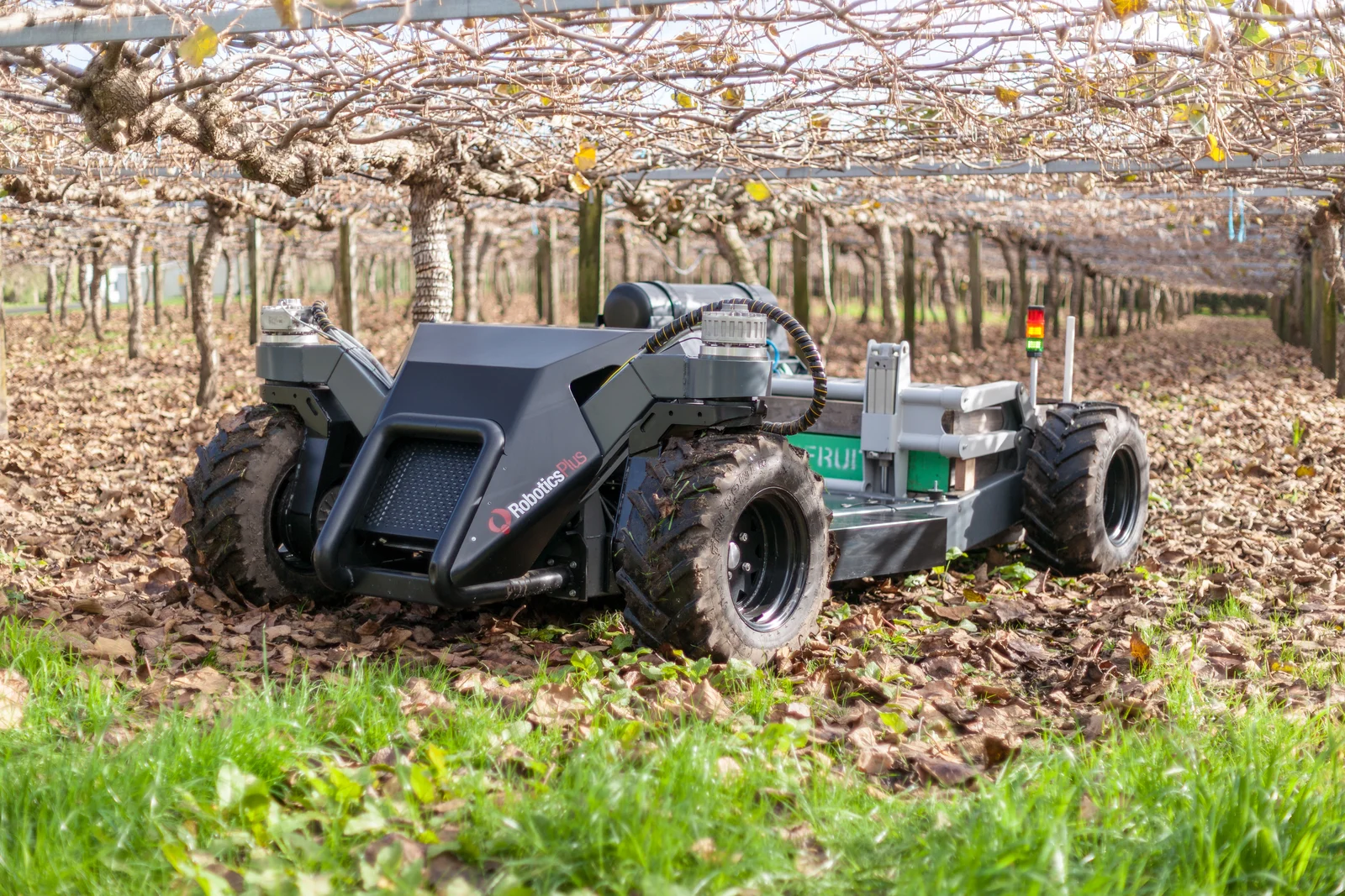
The platform formed the basis of three seasons of field trials in orchards across the Bay of Plenty, carrying both harvesting and pollination modules. Designing, building, and debugging it was a lot of fun. Once development of the platform was finished, my role changed to developing autonomous navigation software.