Autonomous Navigation in Kiwifruit Orchards
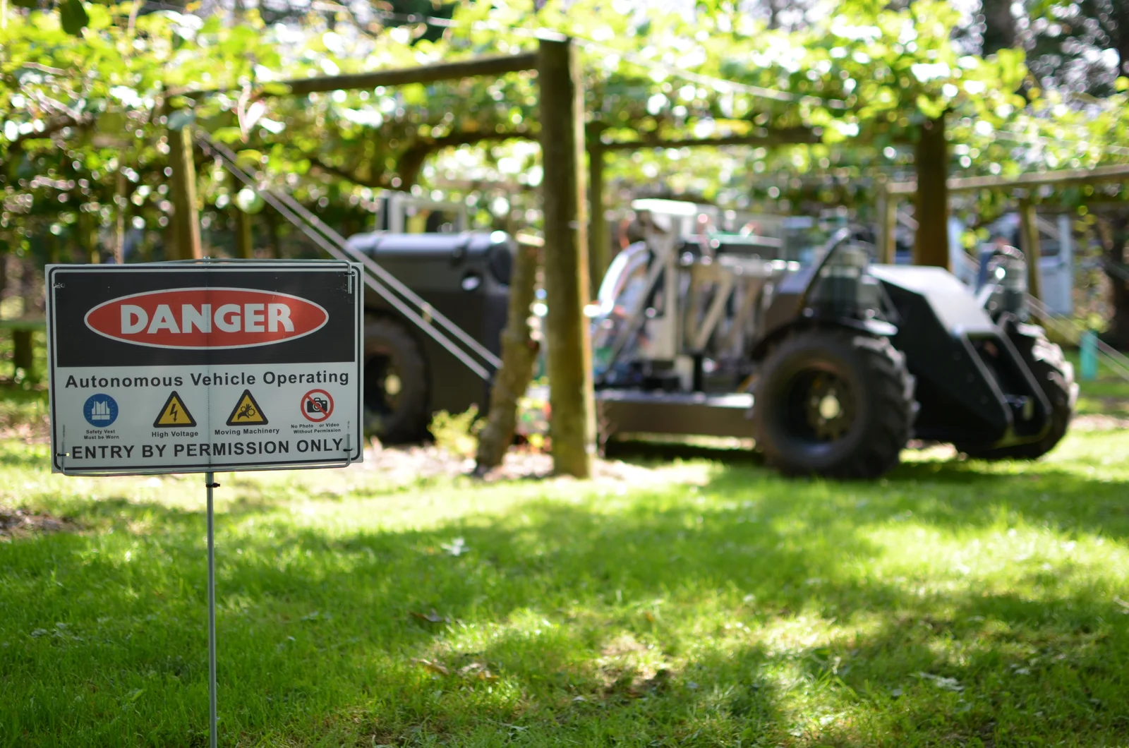
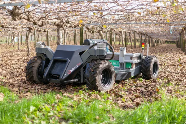
Between 2015 and 2018 a small team of engineers and myself worked on building a series-hybrid multipurpose platform for use in kiwifruit orchards. This post describes my approach to writing the software to make it navigate those orchards autonomously - which are GNSS (Global Navigation Satellite Systems such as GPS, GLONASS, Galileo, and BeiDou) denied during non-winter months due to foliage cover.
If you work with Cartographer pbstream files, check out my Cartographer SLAM Trajectory Editor, a browser tool for fixing misaligned submaps and re-optimising pose graphs.
Goal
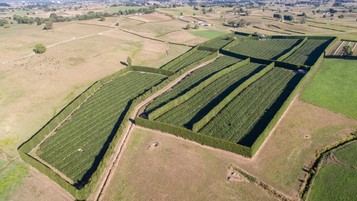
Kiwifruit orchards are usually made from a number of adjacent blocks separated by wind-breaks (the tall dividers, usually hedging, designed to protect the vines from wind). Blocks can be any shape, but are generally made up of linear rows.
Within a block, the platform needed to drive down the centre of each row, turn into the next row, and repeat until all rows have been traversed. The goal was then to navigate to the next block and repeat this process until the entire orchard had been covered.
Breaking this down, the navigation tasks to be done are:
- Row following
- Row-end turns
- Inter-block navigation (moving between blocks)
Inter-block navigation would be handled mostly by GNSS-based navigation paths (basically just following preset waypoints) linking each block and wouldn’t be developed until the intra-block navigation (navigation inside a block) was completed. The immediate goal therefore was to implement row-following and then add the ability to make row-end turns. In practice I got solid row following and a working headland turn planner; integrated a RTK GNSS system and ran some basic tests; and created a simple web-based interface to visualise where the platform was in the orchard. So I can’t say I ended up with a fully working system, but I got reasonably close considering the short timeframe (about 6 months).
Sensing
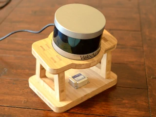
The system was based around a single Velodyne VLP-16 - a multi-layer lidar with 16 scan lines spread over 15 degrees of vertical angle. I mounted it at the front of the platform on a custom bamboo mount alongside an LP-Research IMU, tilted forward so the scan lines fanned out across the ground ahead.
Since the platform is all-wheel-drive, getting reliable odometry information is tricky. As the vehicle drives over various terrain, powered wheels slip. The amount and type of slip can vary dramatically between say concrete or tar-seal and mud or wet grass. The tyre diameter also changes with air pressure, which varies with temperature.
Because of the unpredictability of the wheel odometry, I used Google Cartographer’s built-in odometry output mode, sourced from scan-matching between lidar scans while SLAM is running. This meant that the odometry is calculated directly from the lidar and therefore will be accurate even if the platform is sliding down a hill. Cartographer also builds an occupancy map incrementally as it runs, which was useful for planning headland turns.
Kiwifruit orchards are well suited for scan matching - the regular grid of posts and trunks provides consistent structure for the algorithm to lock onto. But the rows create a lot of linear structure, making translation along the row direction ambiguous. To compensate, I weighted rotation matching 6x higher than translation in the Cartographer configuration, which kept the heading estimate stable. Getting the parameters right took some experimentation. I wrote a script that would systematically sweep through different Cartographer settings, replay the same recorded bag file through each configuration, screenshot the resulting map in RViz, and save the annotated images for comparison. It was a brute-force approach but it worked.
The 360 degree visibility, 200 m range, and 16 vertical scan channels of the VLP-16 were important for enabling the odometry and occupancy map generation. A single channel (2D lidar) would effectively go blind as the ground in front of it curves upward (e.g. at the bottom of a hill).
Row following
At its core, the row-following system just tries to keep the platform centred between the posts on each side of the row. Post placement is the most reliable means of determining row boundaries - vines can sometimes be cut out when they die, the path ahead may not be visible depending on the height of the grass and the curvature of the land. The raw point cloud from the lidar contains posts, trunks, canopy, ground, weeds, nearby people and the platform’s own body and general noise. In order to find the posts amongst all the data coming back, we first need to know where the ground is.
To find the ground, we start by removing points that hit the platform itself - a bounding box around the robot’s footprint takes care of that. Then comes ground detection, which is probably the most involved part of the pipeline. For each point in the cloud, a cone is projected upward from it and any nearby points falling inside that cone are deleted. After iterating over every point, what remains are the locally-lowest returns - points that are on or near the ground. These ground points are plotted into a 2D height map using OpenCV, with each pixel storing a floating-point height value. Most of the map is unknown. To fill in the gaps and build a continuous ground surface, I used iterative Gaussian blurring - starting with a large kernel to establish the broad terrain shape, then progressively smaller kernels to refine detail. After each blur pass, the known ground point values are reset to their measured heights, which constrains the surface to pass through the actual data. This repeats until the known values stop changing, at which point the surface has converged.
With the 2D surface created, it’s converted back into 3D and everything gets filtered by a height threshold above it. Anything below weed level is discarded. Anything up in the canopy is discarded. What’s left is mostly posts and trunks - the structural features that define the rows. This filtered point cloud gets published on two paths: one feeds into the SLAM system for mapping and odometry, and the other gets converted into a 2D occupancy grid for the row follower and path planner.
The following video walks through each stage of the processing pipeline, from the raw VLP-16 point cloud through ground segmentation, ground surface fitting, height filtering, and obstacle detection.
I built two approaches to the actual row detection. The simpler one fits two lines to the obstacle data using RANSAC - one for each side of the row - and computes the midline. It’s fast and works well when the data is clean, but it needs two clearly visible row edges and can’t handle messy or sparse data gracefully.
The more robust approach works by detecting the geometric structure of the orchard. Posts and trunks in a kiwifruit orchard form a regular pattern: pairs on either side of the row, spaced at roughly consistent intervals. The algorithm finds groups of four points that form rectangles with the right dimensions and orientation (a “bay” between two post pairs), chains those bays together into lattices representing continuous sections of row, and scores each chain on linearity, area consistency, and squareness. The highest-scoring chain is taken as the current row.
The steering target - the “carrot” - is placed at the midpoint of the furthest detected bay in the best chain. As the platform moves forward, new bays come into view and the carrot advances. The vehicle steers toward it with a simple proportional controller: steering angle equals the angle to the carrot plus a lateral offset correction, plus a small mechanical compensation for the platform not tracking perfectly straight. Speed ramps down as the carrot gets closer, and if it drops below 5 m away the platform stops - that’s the end-of-row detection.
I tested the row follower over multiple days in different orchards and conditions and it worked every time. The bay-detection approach was reliable enough that I never saw it lose the row or steer into a post. I didn’t run formal repeatability trials - but in practical terms it just worked.
The following video shows the full system running in real-time in an orchard, with a camera view alongside the RViz visualisation of the lidar processing and row detection.
Headland turns
With row following able to reliably get the platform to the end of a row, it was time to get the vehicle into the next row. The headland space (area between the rows and the block boundary) is cluttered with posts, trunks, and canopy supports, and the platform’s turning circle is about 3.2 m, which doesn’t leave much room.
I needed the turns to be planned automatically using the state of the SLAM occupancy map. As the platform drives through the orchard, Cartographer builds up this occupancy map of the surrounding structure - meaning that the orchard doesn’t need to be pre-mapped and that the data is current. The turn planner takes this map, a start pose (the end of the current row), and a target pose (the start of the next row), and finds a collision-free path between them. The following video shows the occupancy map being built up as the vehicle drives (in black and white), then overlays the collected point-cloud (in green) to illustrate the difference between the height-clipped occupancy map and the raw lidar data.
The path is modelled as a sequence of straight and arc segments. A Nelder-Mead optimiser adjusts the segment lengths, radii, and angles to minimise collision overlap, which is checked by stamping a bitmap of the platform’s physical footprint (rotated to 1000 discrete orientations) onto the obstacle map at each pose along the candidate path. If the footprint overlaps an obstacle at any point, the cost goes up. It also tries to minimise the overall length of the turn, just to favour more efficient turns.
I validated the turn planner on recorded bag data and it produced viable paths through the headland space. The optimiser would reliably converge on valid turns that moved the platform between rows, avoiding posts with reasonable clearance. Unfortunately I never got to test it on the platform out in the orchard - hence the lack of video. By this stage the project was winding down, I was preparing to move overseas, and I was introducing a new PhD student to the platform while documenting the system for handover.