Camera-based Key Duplication
Can you copy a key from a photo? It turns out you can. I wanted to try it for myself and see if I could use my CNC milling machine to cut the key from a blank key purchased in a hardware store. The duplicated key worked perfectly on the first try. And yes, this guide is showing you how to break into my house.
Briefly
To duplicate the key, this guide will take you through each of the following steps:- Calibrate the camera
- Photograph the key
- Trace the key outline
- Determine profile to be cut from blank key
- Create the toolpaths for the CNC machine.
- Cut the blank key
The first step of calibrating the camera was unnecessary with the camera setup I used. The corrections had almost no impact on the image I took, but I'd still reccomend doing them. With lower quality pictures or different lenses, this calibration will becoming increasingly important. I used a Nikon D7000 DSLR camera with a Nikkor 16-85mm lens set at 85mm. Calibration of the camera and lens was done by photographing a checkerboard and running an OpenCV camera calibration script on the checkerboard images. I found that displaying the checkerboard on a computer screen worked quite well. Inkscape was used to trace the key outline and generate CAD files (DXF format). Solidworks and HSMWorks was used to model the key and create the toolpaths for the CNC machine. An OmioCNC X82200 EPL CNC machine was then used to cut the key profile.
Camera calibration
The point of camera calibration is to determine how images from a particular camera are distorted. Sources of distortion can be the lens, think fish-eye lenses like a Go-Pro, and alignment of the image sensor to the lens. To account for this, the camera used to photograph the key was also used to photograph a checkerboard pattern from a variety of distances and orientations. Those images were then fed into a Python script that opened these images, finds the corners of the checkerboard patterns. This step was probably not necessary for the quality of photo I took of the key, but was a good exercise anyway.
Photographing the key
Using the highest focal length I had access to (85mm) I took a photo of the target key with the smallest aperture setting on the camera. A high focal length was used to help minimise any lens distortion resulting from a wide field of view. The small aperture was used because it puts everything in focus and increases the exposure time. With a long exposure time I could move a light source around to reduce shadowing. An exposure time of about three seconds was used with the camera mounted on a tripod. The result is shown above.
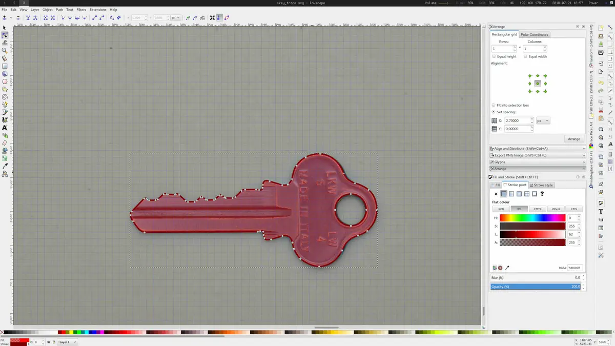
Trace the key outline
The undistorted photo was imported into Inkscape and rescaled to match the dimensions of the actual key. In a way this was cheating as I measured the length of the target key using vernier callipers. If you don't have access to the physical key you could measure the blank key, or place a fiducial marker (such as a ruler) in the image at time of capture. The traced vector path was then exported from Inkscape as a DXF file for importing into SolidWorks.
Determine Cutting Profile

This could be done either in the CAD package or Inkscape. For illustration purposes I've shown the cutting profile as created in Inkscape, but for creating the cutting profile this was done in SolidWorks. HSMWorks (a CAM package that runs inside SolidWorks) was used to generate the machining toolpaths. The first pass was a rough clearing operation to remove most of the material. The second pass was a contoured profile cut that left the desired contour.
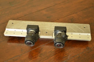
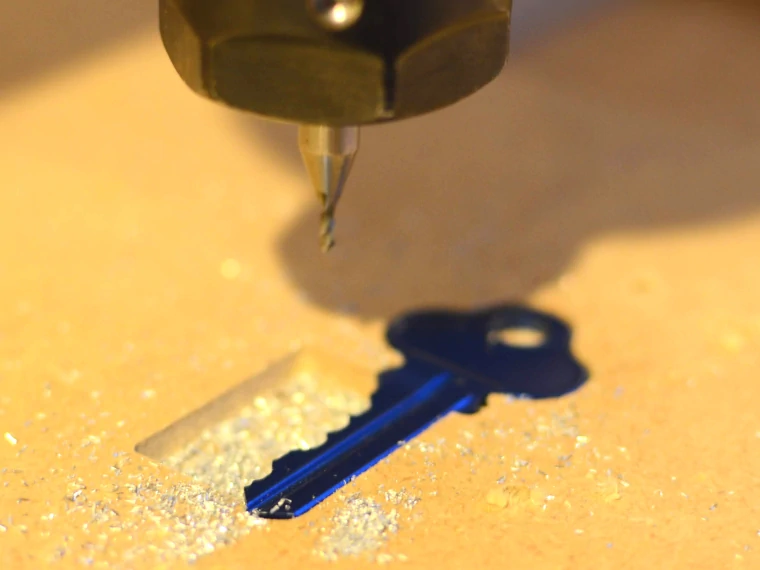
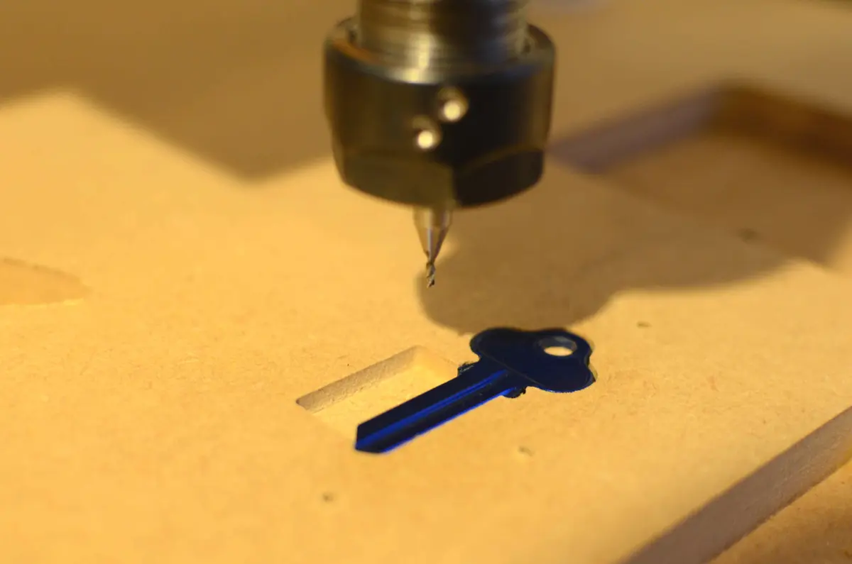
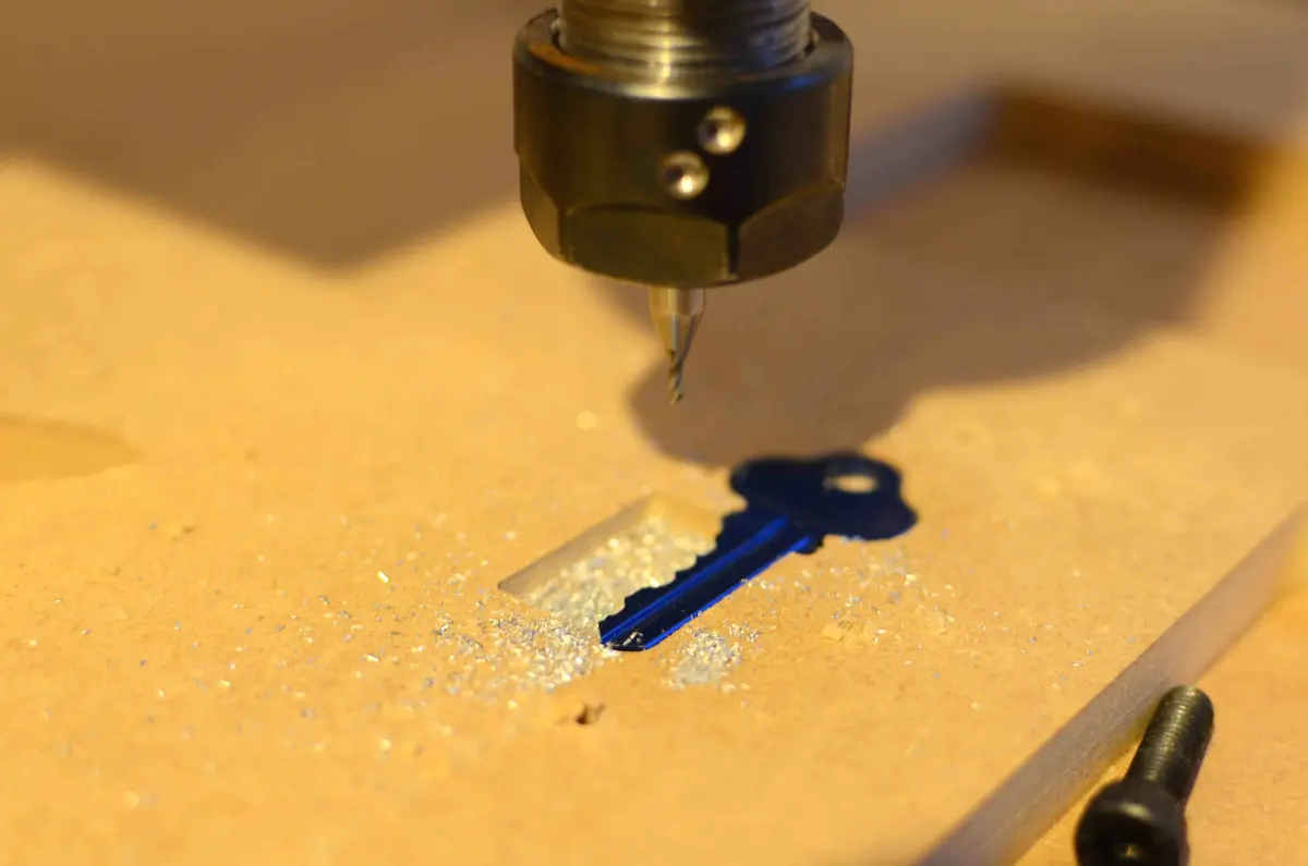
Cut the blank key
To hold the key down I cut the shape of the key out from a piece of MDF. A well was cut into the MDF underneath where the profile was to be cut. To keep the key from jumping out of its I screwed a piece of wood over the top while cutting. One mistake I made was assuming that the dimensions of the blank key would be the same as the target key - they wern't. This meant that the profile wasn't cut in the right spot.
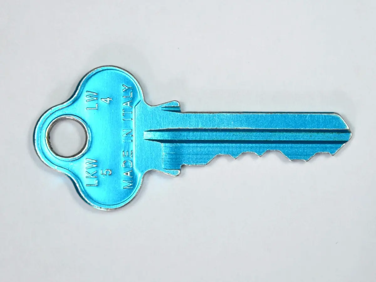
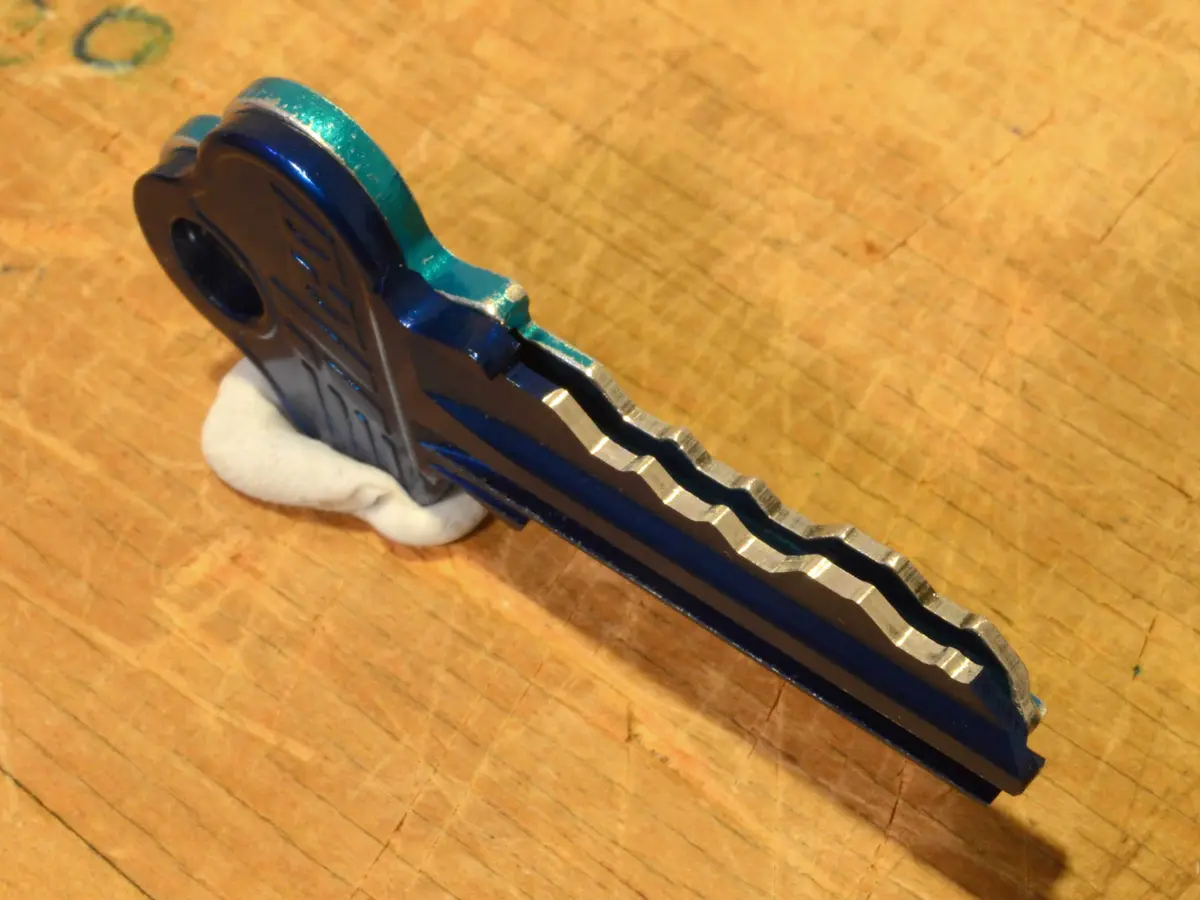
Result
I'm really happy with the shape of the contour in the new key (front), it's smooth and follows the original contours very well. You can see the misalignment between the keys when looking at the fronf of the key (notice the front key sticks out a millimeter or so further). Luckily, the position error of the contour didn't affect the operation of the key, as the following video proves.
Camera Calibration and Image Undistortion
The code used to calibrate the camera and undistort the photo of the key is given below. This code came straight from the OpenCV camera calibration tutorial so there is nothing special here. I have put it here purely for convenience.
import numpy as np
import cv2
import glob
import os
import sys

# Termination criteria
criteria = (cv2.TERM_CRITERIA_EPS + cv2.TERM_CRITERIA_MAX_ITER, 30, 0.001)

# Prepare object points, like (0,0,0), (1,0,0), (2,0,0) ....,(6,5,0)
objp = np.zeros((6*8, 3), np.float32)
objp[:, :2] = np.mgrid[0:8, 0:6].T.reshape(-1, 2)

# Arrays to store object points and image points from all the images.
objpoints = []  # 3d point in real world space
imgpoints = []  # 2d points in image plane.

images = glob.glob('*.JPG')

for fname in images:
    print(fname)

for fname in images:
    img = cv2.imread(fname)
    print("Opened", fname)

    gray = cv2.cvtColor(img, cv2.COLOR_BGR2GRAY)
    print("Converted to grey")

    # Find the chess board corners
    ret, corners = cv2.findChessboardCorners(gray, (8, 6), None)

    # If found, add object points, image points (after refining them)
    if ret == True:
        print("Found corners")
        objpoints.append(objp)
        img1 = img.copy()
        img2 = img.copy()
        cv2.drawChessboardCorners(img1, (8, 6), corners, ret)
        cv2.cornerSubPix(gray, corners, (11, 11), (-1, -1), criteria)
        cv2.drawChessboardCorners(img2, (8, 6), corners, ret)
        imgpoints.append(corners)
        cv2.imwrite('found/'+fname, img)
    else:
        cv2.imwrite('not_found/'+fname, img)
        print("Corners not found")

ret, mtx, dist, rvecs, tvecs = cv2.calibrateCamera(
    objpoints, imgpoints, gray.shape[::-1], None, None)

images = glob.glob('keys/*.JPG')

for fname in images:
    print(fname)

for fname in images:
    img = cv2.imread(fname)
    h, w = img.shape[:2]
    newcameramtx, roi = cv2.getOptimalNewCameraMatrix(
        mtx, dist, (w, h), 1, (w, h))

    # Undistort
    dst = cv2.undistort(img, mtx, dist, None, newcameramtx)

    # Crop the image
    x, y, w, h = roi
    dst = dst[y:y+h, x:x+w]
    cv2.imwrite(fname[:-4]+'_undistorted_shortest.JPG', dst)

    # Undistort
    mapx, mapy = cv2.initUndistortRectifyMap(
        mtx, dist, None, newcameramtx, (w, h), 5)
    dst = cv2.remap(img, mapx, mapy, cv2.INTER_LINEAR)

    # Crop the image
    x, y, w, h = roi
    dst = dst[y:y+h, x:x+w]
    cv2.imwrite(fname[:-4]+'_undistorted_remap.JPG', dst)

cv2.destroyAllWindows()